Solar® Total Shoulder System Upper Extremity Surgical Protocol (1)
|
|
|
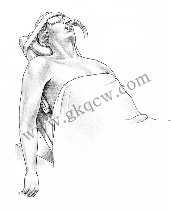
Fig 1. Patient Positioning:The back is flexed 30° to 45°, the legs are padded and bent |
 |
|
Fig 2. Patient Positioning:A half liter IV bag or surgical towels are placed beneath the involved scapula to improve exposure of the articular surface. |
|
|
|
Fig 3. This begins 3-4cm medial to the acromioclavicular joint coursing distally over the coracoid process and along the deltopectoral fold.You will note that the cephalic vein ismedial to the coracoid. |
|
|
|
Fig 4. The cephalic vein is identified and taken laterally with the deltoid. |
|
|
|
Fig 5. A self-retaining or Richardson type retractor may be placed beneath the pectoralis medially and the deltoid laterally. |
|
|
|
Fig 6. This allows additional exposure of the rotator interval and the anterior capsule. |
|
|
|
Fig 7. At this point, it is advisable to palpate and, if possible, visualize the axillary nerve as it courses along the superficial surface of the subscapularis down into the axillary fold inferiorly |
|
|
|
Fig 8. If there is excessive tension on the pectoralis major, the proximal two-thirds may be released at this point using electrocautery. |
|
|
|
Fig 9. A horizontal limb, both superiorly and inferiorly, is then created and traction sutures are placed. |
|
|
|
Fig 10. This is best accomplished by placing a retractor within the capsule at the inferior margin of the humeral head, externally rotating the arm, adducting and releasing that capsule intra-articularly, thus avoiding injury to the extracapsular axillary nerve. |
|
|
|
Fig 11. The subscapularis is longitudinally dissected off the underlying tuberosity at the level of and immediately adjacent to the biceps tendon, a distance of approximately 1 to 2cm. |
|
|
|
Fig 12. At the time of closure, the medial limb of the subscapularis is repaired to the lateral margin of the capsule, thus lengthening the anterior capsule 1 to 2cm and increasing external rotation by 20°–30°. |
|
|
|
|
|
Fig 13. By flexing the elbow 90° and externally rotating the arm 30°–40°, the humeral head cut is made at right angles to the plane of the shaft and head, thereby achieving 30°-40° of retroversion. |
|
|
|
Fig 14. The guide can be removed and the cut is completed; any residual osteophytes are resected. It is recommended that the resected head be saved for later comparison and sizing of the modular head. |
|
|
|
Fig 15. Remaining labral tissue is excised and the margins of the glenoid are defined. |
Continued by:
(史赛克 Solar 全肩置换系统(二))
http://www.gkqcw.cn/gkwinclude/show.asp?id=210
 |
 |
|
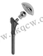
Solar Bipolar Shoulder Replacement |
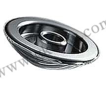
Solar Humeral Head detail |
 |
 |
|
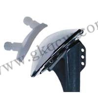
Solar Shoulder Pegged Glenoid Component |
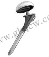
Solar Stem and Dual Offset Head |