Solar® Total Shoulder System Upper Extremity Surgical Protocol (2)
Continued by :
【史赛克 Solar 全肩置换系统(一)】
http://www.gkqcw.cn/gkwinclude/show.asp?id=201
|
|
|
Fig 16. In cases where residual glenoid cartilage is present, a curette is used to remove the cartilage, then the spherical reamer is used to prepare the glenoid face (not fossa). |
|
|
|
Fig 17. After glenoid sizing is completed with the surface trials, the superior/inferior and anterior/posterior axis is marked. |
|
|
|
Fig 18. The superior drill hole is prepared first, using the universal drill/driver. |
|
|
|
Fig 19. Each of the peg holes is checked to make certain that there is no break in the cortical shell. |
|
|
|
|
|
Fig 20. A single batch of polymethylmethacrylate is mixed, the Gelfoam™ is removed and each of the holes is pressurized using a cement delivery |
|
|
|
Fig 21. In cases where residual glenoid cartilage or a non-uniform glenoid surface is present, a spherical reamer is used to prepare the glenoid fossa and provide a uniform surface for instrumentation and implant placement. |
|
|
|
Fig 22. When the appropriate coverage and size has been determined, a |
|
|
|
Fig 23. The appropriate sized keeled glenoid guide is located on the glenoid fossa and the preparation is then marked using methylene blue or electrocautery. |
|
|
|
Fig 24. The appropriate sized keeled glenoid trial is then introduced in the preparation and a trial reduction is performed to make certain there is a uniform seating of the component and that the keel is not bottoming out. |
|
|
|
Fig 25. A single batch of polymethylmethacrylate is mixed, the Gelfoam™ |
|
|
|
Fig 26. The implant is then placed and held until polymerization is complete. |
|
|
|
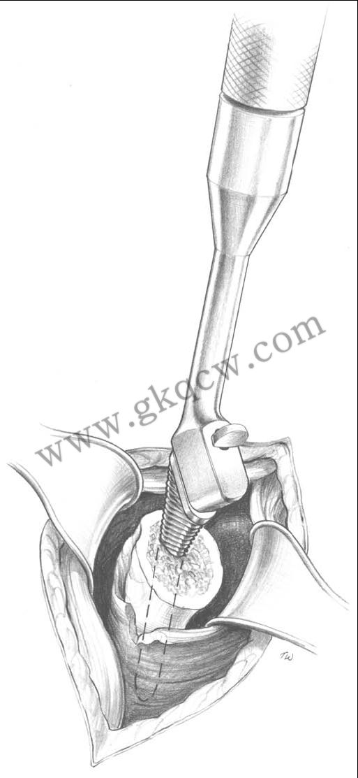
Fig 27. If a long stem prosthesis is indicated, reaming depth is to the circumferential groove positioned at the top of the reamer shaft. |
 |
|
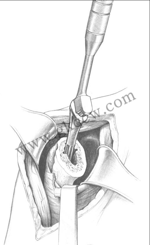
Fig 28. The broach should be seated to the circumferential groove around the proximal section. Do not seat the broach beyond this line. |
|
|
|
Fig 29. The last broach used for reaming can be left in place and modular head trials can be tested. |
|
|
|
|
|
Fig 30. The sizing of the modular head is important for success of this procedure. The previously resected head is compared with the modular trial head to determine both width and height.When a glenoid is used, this lateralizes the joint line so the humeral head height will be 4mm less than the resected head. |
|
|
|
Fig 31. Only one fin cutter needs to be introduced; which should match the last size of broach and reamer used. |
|
|
|
Fig 32. Continue to introduce until final placement is achieved. Be sure to remove any excess cement. |
 |
|
Fig 33. Final seating of the implant is achieved using the stem impactor as mentioned above. |
|
|
| Fig 34.Several sharp mallet blows are used to seat the head. Be sure the angle of the driver is in line with the axis of the trunnion (90° to collar face). |