The ITST Intramedullary Nail System is designed to treat unstable,comminuted,proximal fractures
of the femur,specifically,the Intertrochanteric and Subtrochanteric regions,thereby combining many of the features of an intramedullary nail and hip screw system. The implant supports the anatomic reduction and internal fixation of the femoral head and neck and provides anti-rotational stability for many difficult fracture situations.
The ITST Intramedullary Nail System features a sliding or non-sliding Lag Screw,to help allow for neck fracture settlement,while preventing fragment impaction. System includes options for dynamic and static distal locking.
Manufactured from high strength stainless steel alloy(22-13-5),the ITST intramedullary nail implants are available in a wide range of diameters,as well as short and long lengths to accommodate total joint prostheses. Most femoral neck-shaft angles measure 130˚.The ITST Lag Screw was designed to mimic this angle for use in the majority of patients.In cases where appropriate, a 6.5mm Anti-Rotation Screw is available for use in combination with the 11mm Lag Screw to help stabilize fracture fragments.
Indications
The ITST Intramedullary Nail is indicated for use in a variety of femoral fractures, such as:
●Subtrochanteric Fractures
●Intertrochanteric Fractures
●Comminuted Fractures
●Segmental Fractures
●Fractures with Bone Loss
●Proximal and Distal Fractures
●Nonunions
WARNING:The surgeon should beaware that the use of the system in osteoporotic bone, nonanatomic reductions, or improper placement of the nail-screw construct could increase the risk of failure or cut out of the implant.
Contraindications
Contraindications include:
●Femoral fractures involving the knee joint
●A medullary canal obliterated by a previous fracture or tumor
●Femoral shaft having grossly abnormal,excessive bow(i.e.,curvature deformity)
The implant is contraindicated for use in medial neck fractures. This implant may not provide the required/desired stability when used to treat some femoral neck fractures types.
Overt systemic infection is an absolute contraindication.For patients that exhibit any of the following,systemic infection must be ruled out to minimize the potential hematogenous spread to the implant site:
●Fever and/or local inflammation signs
●Rapid joint destruction or bone absorption apparent on roentgenograms
●Elevation of sedimentation rate or Creactive protein unexplained by other diseases
●Elevation of White Blood Cells (WBS) and/or marked shift in WBC differential
Use of this device is contraindicated in patients with active infection at sites such as the genitourinary tract, pulmonary system,skin, or other sites because hematogenous spread may occur. The foci of infection must be treated and the infection resolved prior to surgery. Routine prophylactic antibiotic treatment immediately before, during, and after surgery may be especially useful for these patients.
Surgical Technique
Preoperative Planning
The ITST Femoral Fixation System implants are designed to place the Lag Screw at 130˚,with15˚ of anteversion on the long nails, to accommodate the most common anatomic femoral neck angle,while minimizing inventory requirements.A/P and lateral C-arm images should be obtained prior to the surgical procedure.
NOTE:The suitability of this implant for the patient should be determined by templating prior to surgery using X-rays of the affected femur.
An A/P preoperative X-ray should be taken of the contralateral hip or of the affected limb once an anatomic reduction has been achieved.
X-rays taken at a 36-inch distance from the source result in 10-15 percent magnification of the bone .An Ossimeter,which takes this magnification into account, should be used to help determine the actual nail length and diameter to be used. The angle of the intersection of the femoral shaft axis and femoral neck axis should be observed. The ITST Templates reflect a 15 percent magnification of actual size.
Patient Positioning
The patient may be placed in either the supine (free legged or traction)or lateral (traction) position.
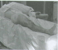
SUPINE FREE LEGGED - Place the patient supine on a radiolucent table (Fig.1).The table should not have a central pole or metal sidebars . Place the patient's buttock next to the edge of the table with a radiolucent bump (not a bean bag) under the buttock. The eccentric position and elevated buttock improves starting site posi-tion and reduces drape encroachment. Furthermore,the elevated buttock enhances fluoroscopic lateral viewing of the femoral head and neck. The ipsilateral upper trunk and extremity should angle towards the contralateral shoulder. The ipsilateral
arm should be placed above the chest on an arm holder or on a pillow with stockinet. This upper extremity placement improves starting point entry and unencumbered implant insertion.
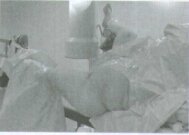
SUPINE TRACTION ON FRACTURE
TABLE - Place the patient supine on the fracture table (Fig.2).Pad all areas of potential pressure. Flex and abduct the non-injured leg onto a well padded leg holder .Or , place the non-injured leg into a scissor type position.
Position the buttock of the injured leg as close to the edge of the table as possible.Some tables will allow for an eccentric peroneal post connection to the table. Make sure the peroneal post is padded and wide in order to dissipate the pressure on the groin area.
Place the injured leg into skeletal traction (distal femoral or proximal tibial)or boot-traction.The ipsilateral arm should be placed above the chest on an arm holder or on a pillow with stockinet.
(3)LATERAL TRACTION ON FRACTURE
TABLE-Use the radiolucent table with a radiolucent peroneal post. Place the traction boots on the patient during anesthesia induction. Turn the patient in a lateral position,with the operative leg over the over the top of the peroneal post. Attach the boots to the table with straight traction applied through the boots.
If heavy traction is necessary, a pin is placed in the distal femur and the knee is flexed, applying traction through the pin.Flex and adduct the operative leg. Straighten the non-operative leg in line with the body. Rotate the patella slightly inwards towards the floor, to help prevent an external rotation deformity. Bring the C-arm in perpendicular to the long axis of the femur. When moving proximally and distally, the entire C-arm is moved, to stay perpendicular to the long axis,To visualize the proximal femur and the head, rotate the C-arm 15˚ over the top and tilted 45˚cephalad.
Patient Positioning for Standard Technique The patient should be placed in either the supine or lateral decubitus position on the table. The sacral rest and perineal post should be well padded. In multiple trauma patients,the supine position may be used for easier access to the patient's airway, as well as to facilitate the treatment of other injuries. The supine position also facilitates fracture reduction and rotational alignment of the femur.
Reduction
It is critical to reduce the fracture before beginning the surgical procedure. An anatomic reduction or a slight valgus reduction of the femoral head and neck,should be seen in the A/P film.Occasionally, a slight sag of the fracture may be seen on the lateral view. This should be taken into consideration during the surgical procedure.
Occasionally, flexion of the injured limb will facilitate sagittal reduction. As a rule of thumb, intertrochanteric fractures are locked into position with internal rotation of the leg. The patella should point towards the ceiling.
For Pertrochanteric or Subtrochaneric fractures(especially with involvement of the lesser trochanter)the fracture is reduced with the leg in external rotation. Oblique roll over or roll back fluoroscopic views can assist visualization of proper rotation. This is most important when considering the starting point of the Steinman pins or the steinman pins or cannulated awlinto the femur.
Radiographic Control
NOTE: It is essential to obtain excellent A/P and lateral images of the femoral head and neck prior to beginning the surgery regardless of which patient position is used.
The use of image intensification or other x-ray imaging is required. The image intensifier should be sterile-draped and may be positioned form the contralateral or ipsilateral side of the operating table.
Confirm visualization of the hip as well as the shaft of the femur using image intensification before prepping and draping. Bend the patient's torso away from the affected extremity to improve access to the greater trochanter. If access to the greater trochanter is still inadequate,adduct the affected leg. However, to achieve proper alignment of the fracture, this adducted position must be corrected prior to insertion of the nail.
Prep and Drape
The prep includes the ipsilateral axilla, trunk,buttock, hip, thigh(circumferentially),and knee. The drape should extend up to the axilla with U-shaped drapes. The free trunk and buttock skin improves nail insertion and diminishes guide entrapment on the drapes. Furthermore,the free area increases the freedom for percutaneous insertion and incision closure. The drape should extend past the knee to allow for distal interlock insertion.
Prep and Drape for Standard Technique
Prep and drape similar to the MIS technique, although it is only necessary to drape proximally to the distal portion of the thoracic cavity for the standard technique, not all the way to the axilla. If the patient is obese, Prep and drape to the axilla and use a more proximal entry point.
Fracture Site Reduction After Prep and Drape
An attempt at fracture site reduction should be performed initially to facilitate the starting site placement, central reaming, and nail-screw insertion, The rotation and alignment should have been performed before the prep and drape. In fractures with varus alignment despite traction, placement of the patient in a lateral position of the percutaneous reduction instruments can help assist the reduction. A spike pusher or tenaculum clamp can be inserted through a 25 to 30mm incision to realign the a 25 to 30mm incision to realign the proximal fragment. The classic flexion, abduction, and external rotation of the proximal fragment requires reduction at this the time.A spike pusher or tenaculum clamp in an anterior to posterior direction will help accomplish the reduction.
Starting Point and Steinman Pin lnsertion and Incision Using Long Cannulated Awl
Palpate the line of the femur starting at the greater trochanter. Continue this line of insertion proximally until reaching the level approximating the iliac crest (more proximal with obese patients) (Fig.3).
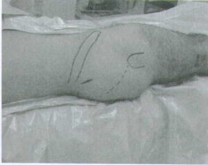
Using a sterile marking pen, mark the line of intersection between these two lines; this corresponds to the insertion site. Insert the 3.2mm terminally threaded Steinman pin through the soft tissues.The correct atarting point on the Ap view is the medial half of the greater trochanter. The correct starting point on the lateral view corresponds to the central half of the femoral neck. An optional cannula can also be used to help guide the pin into the correct position. The cannula is inserted through a 25mm incision at the levet of the iliac crest. The cannula can also be used to protect tissues while reaming.
Incision
Use a # 15 blade to create an incision centered around the Steinman pin. The incision needs to be only 15mm-20mm in length.
Starting Point and Incision for Standard Technique
Begin the skin incision 1cm proximal to the tip of the greater trochanter, and extend it proximally for about 5cm in a longitudinal direction. Continue the incision down through the subcutaneous tissues and split the fascia lata.
Creating the Entry Portal
Insert the terminally threaded Steinman pin through the greater trochanter down to the level of the lesser trochanter(about 8cm). Ream using the 8mm trochanteric reamer (for comminuted fracture lines extending into or around the insertion site)followed by the 17mm trochanteric reamer (initially for fractures without fracture lines extending into the starting site)followed by the 17mm trochanteric reamer (initially for fractures without fracture lines extending into the starting site). The reamers can be inserted freely through the soft tissues or through the cannula. The entry portal should be in line with the planned nail insertion and should line up with the femoral canal on the AP and lateral views (not aiming to the medial or anterior cortices).
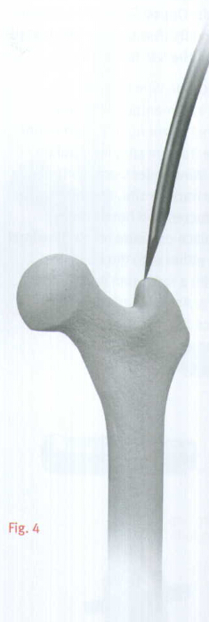
OPTIONAL TECHNIQUE
A cannulated awl can be used instead of a guide wire to create the entry portal. Place the tip of the awl in the selected starting point (tonfirm using bi-planer fluoroscopy).Advance the awl through the greater trochanter into the canal in line with the planned nail insertion (Fig.4).
Guide Wire Placement
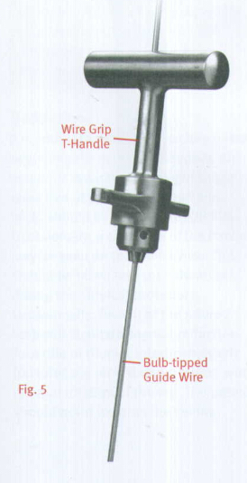
On the back table, attach the 3.0mm Bulb-tipped Guide Wire to the Wire Grip T-Handle,and tighten(Fig.5). The tip of the Guide Wire may be bent to approximately 20˚,to facilitate passage across the fracture site or into the central aspect of the distal femur.
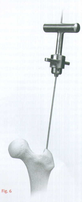
NOTE:If using a cannulated awl, the 3.0mm Bulb-Tipped Guide Wire may be passed directly through the cannulated awl without the 45˚bend(Fig.6).
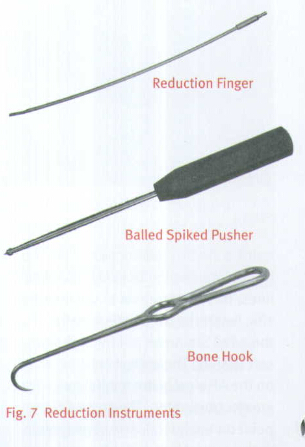
Insert the Guide Wire through the entry hole and manipulate it down the proximal femur across the fracture site. At the fracture site, manipulate the Guide Wire under C-arm control across the fracture site . If reduction of the abducted and flexed hip is difficult, place pressure on the proximal fragment, either with the hand or directly with a reduction rod or other instrument. An alternative technique is to reduce the fracture using the Reduction Instruments shown in Figure 7 .
The reduction finger can also be used to assist in reduction if the surgeon creates an initial oblique starting portal. Once in the distal canal, pass the wire to the distal epiphyseal scar. Gently tap the guide wire into the dense distal bone, so that the wire will not retract with reamer removal.
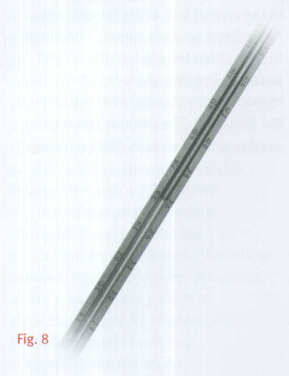
The surgeon determines the proper nail length using the Nail Length Gauge. Slide the gauge over the guide wire until the tip rests along the proximal aspect of the greater trochanter(Fig.8).
Reaming
The ITST MIS Cannula can be inserted into the incision to protect the soft tissue while reaming.
Thread the Centering Bushing into the Cannula and place the Cannula firmly against the bone. Remove Centering Bushing. Ream the femoral canal sequentially in 0.5mm increments using the Long Pressure Sentinel®Intramedullary Reaming System(Fig.9).Ream until cortical chatter is experienced. Based on bone quality and curvature of radius, nail diameter is 1-22mm less than the last reamer used.
 个人中心
个人中心 消息中心
消息中心